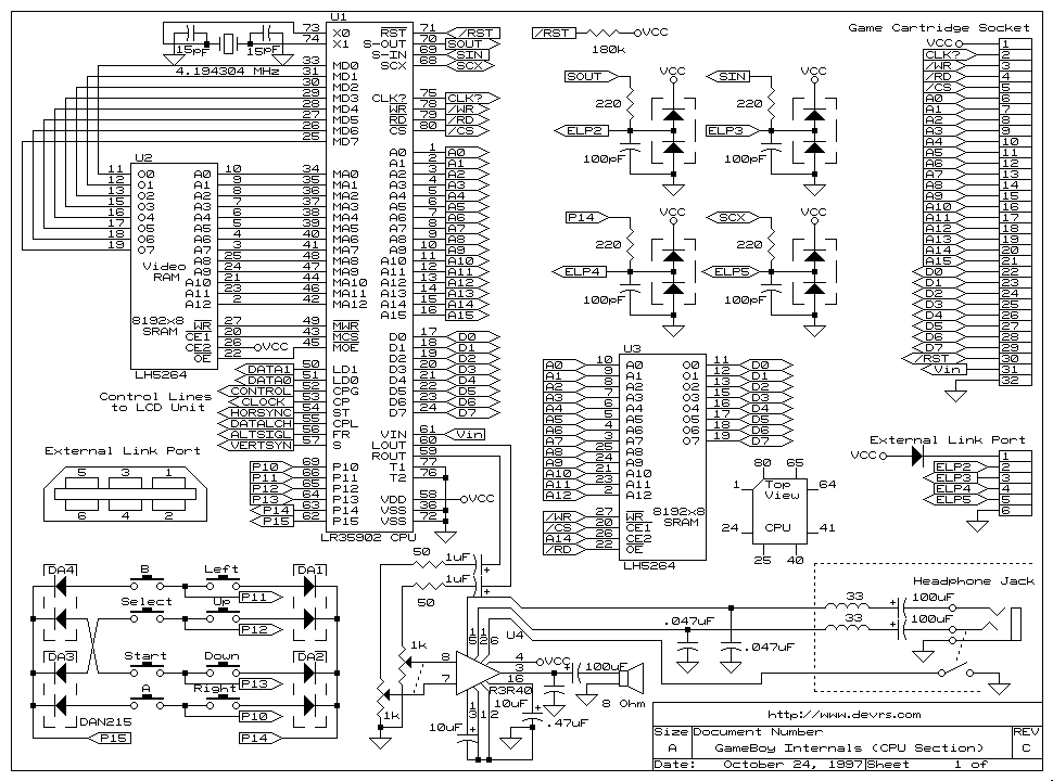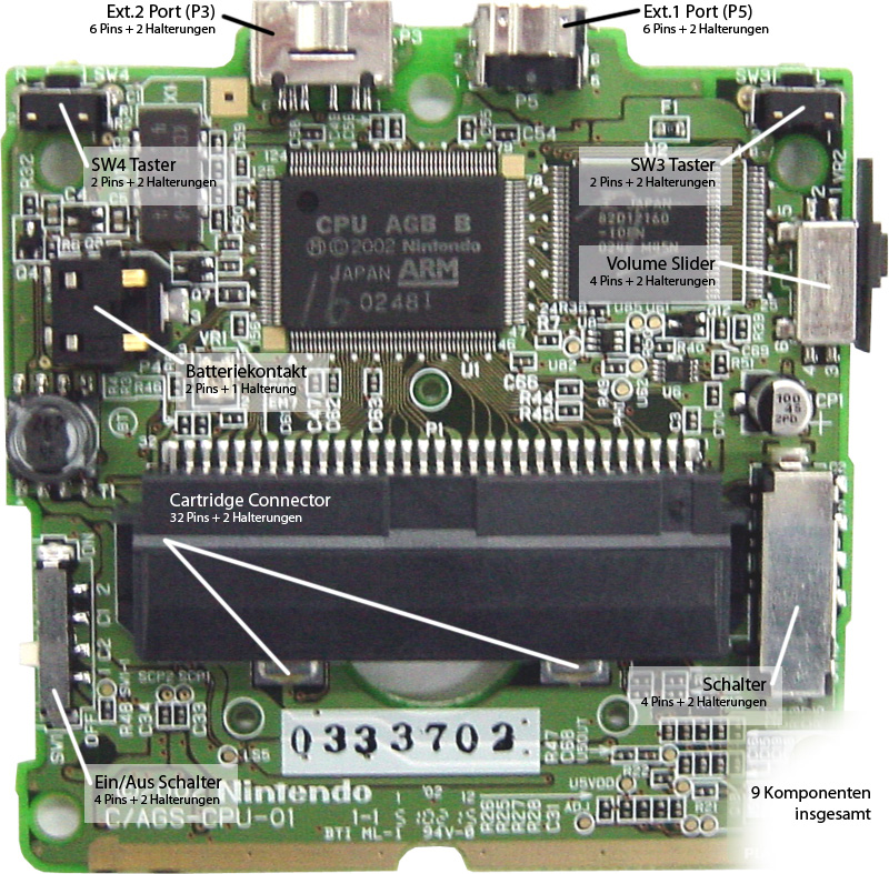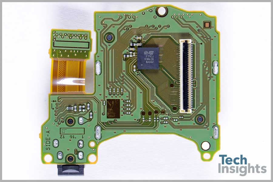

gbhwdb uses unofficial type A1/A2/A3/B/C/D designation, which is also used here. There are several versions of the regulator board, but the board label is not enough to distinguish the different versions. Original Game Boy LCD board (DMG-LCD-06) schematics Original Game Boy DC/DC power board (DC CONV DMG / DC CONV2 DMG)Ĭomponents were identified by desoldering and measuring everything on one board of each type (A/B/C/D). Traced AGS-CPU-11 board SVG Original Game Boy LCD board (DMG-LCD-06)Ĭomponents were identified by desoldering and measuring everything on a DMG-LCD-06 board. Game Boy Advance SP AGS-001 mainboard (AGS-CPU-11) schematics Note: there are several versions of Advance SP mainboards, and these schematics have accurate information only for AGS-CPU-11

Raw notes of MGL-CPU-01 board components Game Boy Advance SP AGS-001 mainboard (AGS-CPU-11)Ĭomponents were identified by desoldering and measuring everything on a AGS-CPU-11 board. Raw notes of MGB-ECPU-01 board components Game Boy Light mainboard (MGL-CPU-01)Ĭomponents were identified by desoldering and measuring everything on an MGL-CPU-01 board. ArcadeTV.Ĭomponents were identified by desoldering and measuring everything on MGB-ECPU-01 and MGB-LCPU-01 boards. Traced based on high-res scans by Alex a.k.a. Game Boy Pocket mainboard (MGB-CPU-01, MGB-ECPU-01, MGB-LCPU-01, MGB-LCPU-02)

Licensed under Creative Commons Attribution 4.0 International.


 0 kommentar(er)
